Inductor Design with Magnetics Powder Cores
For assistance in determining a Magnetics core(s) to use in specific inductor designs, download our Inductor Design tool or contact Magnetics with your Custom Inductor Design request.
Only two parameters of the design application must be known to select a core for a current-limited inductor; inductance required with DC bias and the DC current. Use the following procedure to determine the core size and number of turns.
1. Compute the product of LI2 where:
L = inductance required with DC bias (mH)
I = DC current (A)
2. Locate the LI2 value on the Core Selector Chart. Follow this coordinate to the intersection with the first core size that lies above the diagonal permeability line. This is the smallest core size that can be used.
3. The permeability line is sectioned into standard available core permeabilities. Selecting the permeability indicated will tend to be the best tradeoff between AL and DC bias.
4. Inductance, core size, and permeability are now known. Calculate the number of turns by using the following procedure:
(a) The inductance factor (AL in nH/T2) for the core is obtained from the core data sheet. Determine the minimum AL by using the worst case negative tolerance (generally -8%). With this information, calculate the number of turns needed to obtain the required inductance from:

Where L is required inductance (μH)
(b) Calculate the bias in A•T/cm from:

(c) From the Permeability vs. DC Bias curves (pgs 48-65), determine the rolloff in per unit of initial permeability for the previously calculated bias level. Curve fit equations shown in the catalog (and on our Curve Fit Tool) can simplify this step.
(d) Multiply the required inductance by the per unit rolloff to find the inductance with bias current applied.
(e) Increase the number of turns by dividing the initial number of turns (from step 4(a)) by the percentage roloff. This will yield an inductance close to the required value after steps 4 (b), (c) and (d) are repeated.
(f) Iterate steps 4 (b), (c) and (d) if needed to adjust turns up or down until the biased inductance until it is satisfactorily close to the target.
5. Choose the correct wire size using the Wire Table. Duty cycles below 100% allow smaller wire sizes and lower winding factors, but do not allow smaller core sizes.
6. Design Checks
(a) Winding Factor. To calculate winding factor, multiply the number of turns by the wire area found on the Wire Table to find the total wire area. Divide the total wire area by the core window area to obtain the winding factor of the design. Verify that the winding factor is acceptable by referencing the various winding approaches described here. (Core area and window area can be found on the core datasheet or the catalog page.)
(b) Copper Losses. See pg. 22 for notes on calculating conductor resistance and losses.
(c) Core Losses. See pgs 23-27 for notes on calculating AC core losses If AC losses result in too much heating or low efficiency, then the inductor may be loss-limited rather than current-limited Design alternatives for this case include using a larger core or a lower permeability core to reduce the AC flux density; or using a lower loss material such as MPP or Kool Mμ MAX in place of Kool Mμ, or High Flux in place of XFlux.
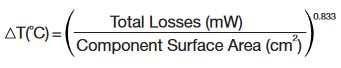
(d) Temperature Rise. Dissipation of the heat generated by conductor and core losses is influenced by many factors. This means there is no simple way to predict temperature rise (▲T) precisely. But the following equation is known to give a useful approximation for a component in still air. Surface areas for cores wound to 40% fill are given with the core data in this catalog.
Core Selection Example
Determine core size and number of turns to meet the following requirement:
(a) Minimum inductance with DC bias of 0.6 mH (600 µH)
(b) DC current of 5.0 A
1. LI2= 0.6 X 5.02=15.0 mH•A2
2. Using the Kool Mμ Toroids LI2 chart, locate 15 mH•A2 on the bottom axis. Following this coordinate vertically results in the selection of 0077083A7 as an appropriate core for the above requirements.
3. From the 0077083A7 core data, the inductance factor (AL) of this core is 81 nH/T2 ± 8%. The minimum AL of this core is 74.5 nH/T2.
4. The number of turns needed to obtain 600 μH at no load is 90 turns. To calculate the number of turns required at full load, determine the DC Bias level:
H=4π N·I / le where le is the path length in mm. The DC bias is 57.5 Oe, yielding 72% of initial permeability from the 60μ Kool Mμ DC bias curve on p. 48. The adjusted turns are 90/0.72 = 125 Turns.
5. Recalculate the DC bias level with 125 turns. The permeability versus DC bias curve shows 58% of initial permeability at 79.8 Oe.
6. Multiply the minimum AL 74.5 nH/T2 by 0.58 to yield effective AL = 43.2 nH/T2. The inductance of this core with 125 turns and with 79.8 Oe will be 675 μH minimum. The inductance requirement has been met.
7. The wire table indicates that 17 AWG is needed to carry 5.0 A with a current density of 500 A/cm2.
125 turns of 17 AWG (wire area = 1.177 mm2) equals a total wire area of 147.1 mm2.
The window area of a 0077083A7 is 427 mm2.
Calculating window fill, 147.1 mm2/427 mm2 corresponds to an approximate 35% winding factor.
A 0077083A7 with 125 turns of 17 AWG is a manufacturable design.