PFC Boost Design
Kool Mu® material’s low loss and relatively high saturation level (10,500 gauss) make it excellent for use in power factor correction circuits (PFC). Here is an example of using Kool Mu in the PFC Boost Design.
Have a question about PFC Design? Ask us here.
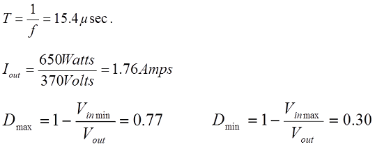
Design Criteria and Input:
Power: 650W
Input: 85-260 Volts DC input
Output: 370 Volts DC output
Frequency: 65 kHz
.png)
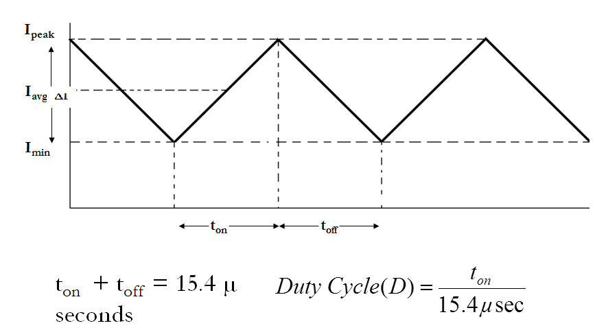
D= Duty Cycle
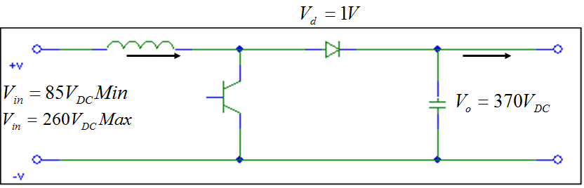
Typical Boost Circuit Schematic:
Design Boost Stage:
1. Examine inductor current.
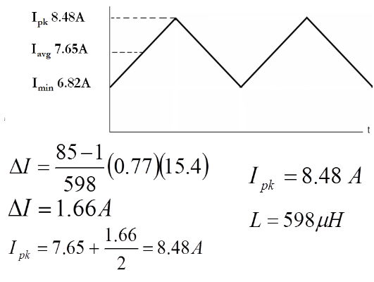
Inductor Current
at Low Line Voltage
at High Line Voltage
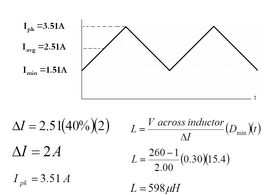
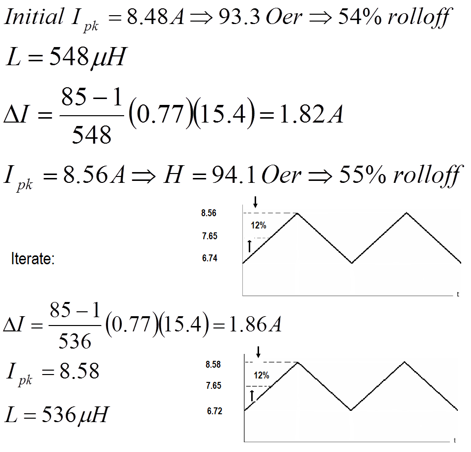
2. Determine the AC ripple permitted.
Max Current Ripple = 40%
This is arbitrary. The inductance and loss calculations depend on this value. Actual result will undershoot because the worst case inductance and ripple do not occur together. Design can be iterated to improve ripple or improve cost/space.
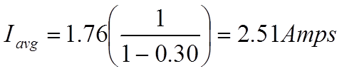
3. Inductance required to support worst-case V ripple. Highest current to be supported.
Looking closer at the Inductance Iin
Equivalent Circuits
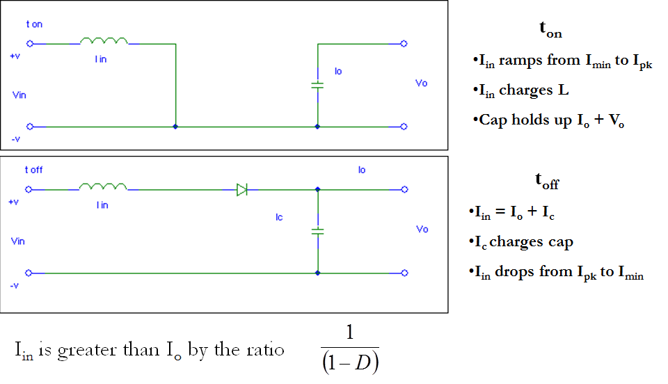
Worst case ripple is at high line voltage
Worst case Ipk is at low line voltage
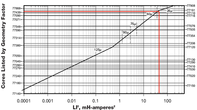
4. Core Selection Process and LI2 Product
LI2=(0.598)(8.48)2=43
From the core selector chart below (also found in our Powder Cores Catalog starting on pg 28), Kool Mu part number: 0077439A7
µ = 60 Ve = 21.3 cm3
AL = 135 Aw = 4.27 cm2
le = 10.74 cm MLT = 8.66 cm (full)
Kool Mu Selector Chart
5. Determine Number of Turns.
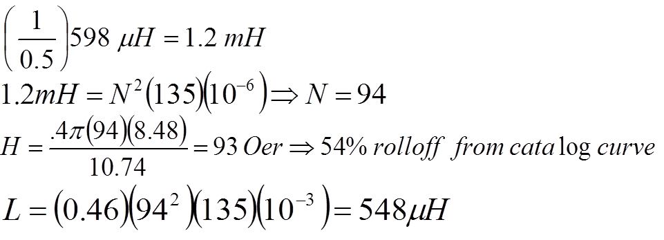
Turns could be added to achieve the 598 µH target, but 548 is not an unreasonable result.
N=94, L at no load = 1190 µH
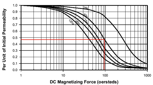
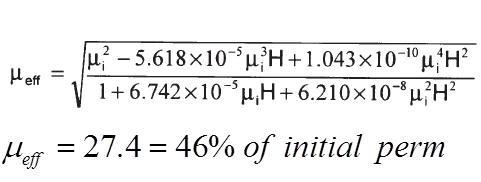
Kool Mu Permeability vs. DC Bias Curve
6. Using the core chosen recalculate inductor current
- At high line voltage
- At low line voltage
High Line Voltage
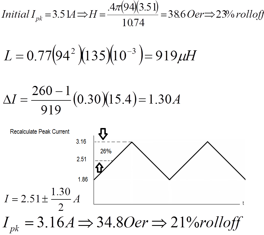
Low Line Voltage
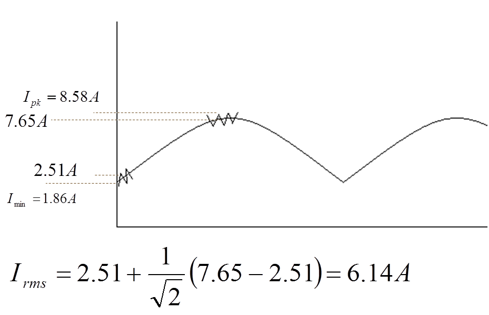
7. Combine results to obtain waveform and RMS current.
8. Choose wire.
For 6.1 A current use AWG #17 Wire
R = 16.57 mΩ/m Wa = 0.0122 cm2
For AWG #16 Wire
R = 13.19 mΩ/m Wa=0.0152 cm2 Fill = 33%
(A larger wire size could be used to have a more nominal window area fill.)
NOTE: AC Ripple at 65 kHz will result in skin effect losses. Multi-strand wire equivalent to the #16 gauge would actually be used.
Flux Density Calculations:
At Low Line Voltage
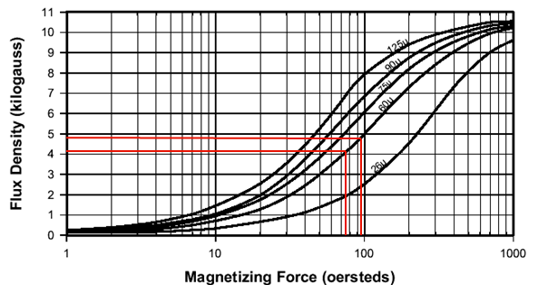
Ipk = 8.58 => Hpk = 94.4 Oer
Imin = 6.72 =>Hpk = 73.9 Oer
From below Normal Magnetization Curve,
Bpk = 4810 Guass, Bmin = 4040 Gauss
1/2ΔB = 385 Guass
At High Line Voltage
Hpk = 30.8 Oer, Hmin = 20.5 Oer
Bpk = 2170 Guass, Bmin = 1340 Guass
1/2ΔB = 415 Guass
Kool Mu Normal Magnetization Curves
9. Calculate Losses - core losses and copper losses.
P = B2f 1.46 for 60u Kool Mu
P = (0.385)2(65)1.46 = 66mW/cm3……High Line
P = (0.145)2(65)1.16 = 76 mW/cm3……Low Line
Ve = 21.3 cm3
Power Loss = (mW/cm3)(cm3)
Core Losses = 1400-1620 mW
Cooper Losses:
For #16 Wire
Rcoil = MLT(N)(R/length)
Rcoil = (8.66 cm/turn)(94T)(0.1319 mΩ/cm)
Rcoil = 107 mΩ
Power Loss copper = (I)2(R)
Pcu = (6.14)2(0.017) = 4030 mW
NOTE: This neglects AC losses. Litz or multistrand wire should be used.
Total losses 5.4 - 5.7 Watts
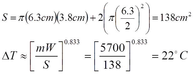
10. Estimated Temperature Rise.
Wound inductor surface area S
OD = 6.3 cm, Height = 3.8 cm
Design Summary:
- Using 0077439A7 Magnetics Kool Mu Toroid
- N=94 turns of multistrand equivalent to AWG#16, giving a fill factor of 33%
- L=1190µH at no load
- L=536µH at peak (8.58A)
- Inductor Max Ripple = 26%
- Core losses = 1.4-1.6 W
- Copper losses = 4.0 W
- ΔT estimate ≈ 22°C
Introduction to power factor correction (PFC) and types of PFC
Have a question about PFC Design? Ask us here.