Power Factor Correction
Why condition power?
There are many good reasons to condition power:
- Business and Industry, such as computers, sensors, controllers and drives.
- Control line voltage.
- Control current distortion.
- Comply with European Standard IEC 555 now IEC/EN 61000-3-2, 61000-3-4. Maximum permissible values for harmonics of the input current.
- Comply with European Standard IEC 555 now IEC/EN 61000-3-3. Limitation of voltage fluctuation and flicker in low voltage supply systems.
- Comply with US Energy Star recommendations
- CNIS China Institute of Standardization.
- Avoid transients, surges, sags, power interruptions and control harmonics.
- Save money.
More reading: Understanding power factor and the need of powder factor correction at Power Systems Design by Arun Ananthampalayam, CUI.
Power Conditioning for Industry
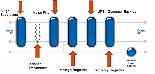
Designed for the type of load it will have to support and may include any or all of these solutions. Starting with surge suppression on the incoming mains, through an isolation transformer, noise filters to the power conditioning circuitry and finally to a UPS system with generator backup for when the power goes out completely.
A system with a linear type power supply will frequently already have an isolation transformer but may be sensitive to voltage fluctuations. These systems will probably need some type of surge diverter and maybe a voltage regulator, too.
Most modern electronic systems, however, have switched mode power supplies (SMPS). This type of power supply technology is largely immune to changes in power line voltage but in the process of making the power supply smaller, more efficient, and cheaper, the isolation transformer has been eliminated from the design. Systems with a switched mode power supply will require, at a minimum, a surge diverter, a noise filter, and an isolation transformer.
Meanwhile, any system in which data is held, edited, or manipulated in some way in volatile memory may need the protection of a battery backup system or UPS to ensure that data can be saved and the system properly shutdown in the event of a power outage.
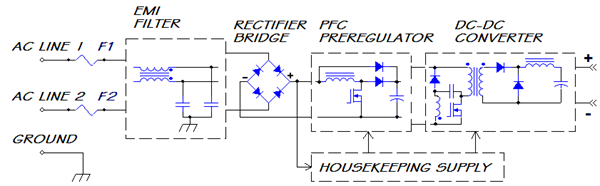
Power Conditioning in SMPS
Power conditioning is also being put onboard in most new devices that have a power supply. Typically there is an input EMI Filter, (Differential and common mode filters) and a half wave or full wave bridge rectifier. Between the rectifier bridge and the DC-DC converter there is typically a Power Factor Correction circuit. SMPS present non-linear impedance to the mains due to the input circuitry. Input is usually half wave or full-Wave rectifier followed by a capacitor that is capable of maintaining the voltage until the next peak comes along to recharge the capacitor. The input pulse of current dumps a large charge during a short time. The capacitor slowly discharges into the load until the cycle repeats.
Types of Power Factor Correction (PFC)
- Passive PFC: Operates at line frequency
- Relatively large size and weight
- Difficult to achieve high PF
- Narrow line voltage range - Active High Frequency PFC: Operates at 20-100 kHz frequency
- High PF ( 0.97 – 0.99)
- Low harmonic distortion
- Small magnetic components - Active Low Frequency PFC: Operates 2 X line frequency 100-200 Hz
- High efficiency; simple circuitry
- DC bus not regulated
- Larger heavier components
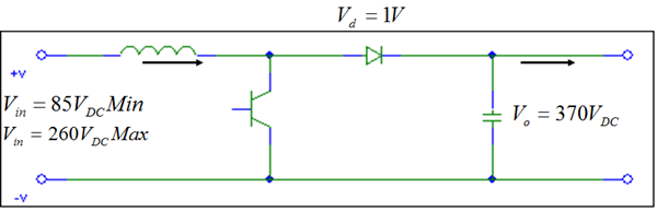
PFC Boost Design Example Using Kool Mu®
Design Criteria and Input:
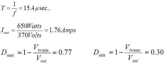
Power: 650W
Input: 85-260 Volts DC input
Output: 370 Volts DC output
Frequency: 65 kHz
D= Duty Cycle
Typical Boost Circuit Schematic:
Design Boost Stage:
- Examine inductor current
- At low line voltage
- At high line voltage - Determine the AC ripple permitted
- Inductance required to support worst-case V ripple
- Highest current to be supported
- Select core
- LI2 product
- Using the core chosen recalculate inductor current
- At low line voltage
- At high line voltage - Combine results to obtain waveform and RMS current
- Choose Wire
- Calculate losses - Core losses + copper losses
- Estimate temperature rise