Learn More about Tape Wound Cores
Please visit the Technical Documents library for the Tape Wound Core Design Manual. Other reference materials including technical bulletins, application notes and white papers are also available for download.
What are Tape Wound Cores?
Tape wound cores are made from thin strips of high permeability nickel-iron alloys such as; Orthonol®, Square Permalloy 80, Supermalloy and Alloy 48, or grain oriented silicon iron known as Magnesil®. Materials are produced in thicknesses from 0.0005” through 0.004”, for a wide range of frequency applications, and are wound into toroidal shapes varying from fractions of a gram to hundreds of kilograms in weight. All materials can be provided in phenolic or plastic, aluminum or insulation coated aluminum, protective cases. Magnesil material is also available unboxed or encapsulated with epoxy. Specific applications for tape wound cores include magnetic amplifiers (MagAmps), converter and inverter transformers, current transformers, and static magnetic devices.
Bobbin cores are miniature tape cores wound from ultra-thin nickel-iron strip on a stainless steel bobbin. Bobbin cores are manufactured from ultra-thin tape (0.000125" to 0.001" thickness) in Permalloy 80 and Orthonol and can be manufactured with widths of 0.031" to 0.250". Core diameters are available down to 0.050" or less on special request. Bobbin cores can switch from positive to negative saturation in a few microseconds or less, making them ideal for logic elements, serial/parallel data conversion, and generation of pulse patterns. Because of their temperature stability, low coercive values, and high saturation densities, they are often superior to other types of cores in computers, high frequency amplifiers, harmonic amplifiers, harmonic generators, pulse transformers, counters, and timers.
Nanocrystalline cores are made from metallic glass materials (FeSiNbCuB) with a crystalline structure and are available from 5mm to 145mm in toroids and split cores. Nanocrystalline cores are a choice solution for applications such as common mode chokes and current transformers as they exhibit high permeability, low power loss, and high saturation. Saturation induction of 1.25T and a wide temperature range mean that nanocrystalline cores are less vulnerable to current imbalance and loss of performance at high temperature. The material’s low AC losses result in excellent efficiency, and the option of durable cases - available in polyester (<130°C) and rynite polyester (<155°C) - makes cores suitable for winding with thick wire.
Amorphous cut cores are made from metallic glass materials without a crystalline structure (as seen in silicon steels, permalloys, orthonol, and nanocrystalline cores). The amorphous atomic structure results in much higher resistivity than what is exhibited by crystalline alloys; therefore, amorphous cut cores offer excellent frequency response and efficiency. Amorphous cut cores are a choice solution for high frequency, low loss applications such as uninterruptible power supplies (UPS), SMPS power factor correction (PFC) chokes, filter inductors, and high frequency power transformers and inductors. Amorphous cut cores are strong in both compression and tension. They resist fracture and corrosion.
What Cases/Coatings are Available for Tape Wound Cores?
Non-Metallic Cases (Case/Coating Code "50")
For superior electrical properties, improved wearing qualities, and high strength, non-metallic cases are widely used as protection for the core material against winding stresses and pressures. Both phenolic and nylon types meet a minimum voltage breakdown of 2000 volts wire-to-wire. The glass-filled nylon types can withstand temperatures to 200°C (392°F) without softening, while the phenolic materials will withstand temperatures up to 125°C (257°F).
Aluminum Cases (Case/Coating Code "51")
Aluminum core cases have great structural strength. A glass epoxy insert, to which the aluminum case is mechanically bonded, forms an airtight seal. These core cases will withstand temperatures to 200°C (392°F), a critical factor in designing for extreme environmental conditions.
Aluminum Case with GVB Epoxy Paint (Case/Coating Code "52")
This case is the same basic construction as the aluminum box, but in addition it has a thin, epoxy-type, protective coating surrounding the case. This finish adds no more than 0.015" to the OD, subtracts no more than 0.015" from the ID, nor adds more than 0.020" to the height.
GVB epoxy paint finish offers a guaranteed minimum voltage breakdown of 2000 volts wire-to-wire. This coating will withstand temperatures as high as 200°C (392°F) and as low as -65°C (-85°F) with an operating life of greater than 20,000 hours.
Uncased/Bare Cores (Case/Coating Code "53")
Uncased cores offer a maximum window area. They also offer a slightly smaller package and lower cost where slight deterioration of properties after winding can be tolerated.
Because of the extreme sensitivity of nickel-iron cores to winding stresses and pressures, such cores are not available in an uncased state. Magnesil cores are not as susceptible to these pressures and are available without cases.
Encapsulated (Red Epoxy) Cores (Case/Coating Code "54")
Encapsulated cores have a guaranteed minimum voltage breakdown of 1000 volts from core to winding. The temperature rating of this finish is 125°C (257°F).
Only Magnesil cores are available in encapsulated form. This protection is a tough, hard epoxy which adheres rigidly to the core, allowing the winder to wind directly over the core without prior taping. A smooth radius prevents wire insulation from damage.
Below is a quick reference for available combinations of materials, cases, and gauges.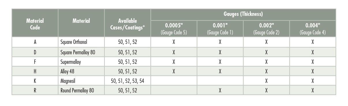


Are amorphous and nanocrystalline tape wound cores available?
Magnetics also offers tape wound cores made with amorphous materials like Metlas® and nanocrystalline materials like Finemet® or Vitroperm®. Contact Magnetics for more information on availability of amorphous and nanocrystalline cores.
What are some common misconceptions of tape wound core testing?
A common pitfall on testing square loop tape wound cores is to measure the inductance or AL value. Although this is a common measurement for ferrite and powder core materials, which are round loop materials, it is not a valid measurement for square loop materials like Permalloy, Orthonol, Magnesil, etc. An inductance measurement can be obtained on a square loop material, but it does not give any indication of the functional magnetic properties.
Additionally, the inductance measurement of the square loop material is not repeatable. This is due to the remanance of the core (Br). Any measurement, leaves the core at some Br rather than the origin, see the figure below. Factors such as application and removal of a DC bias field, proximity to a permanent magnet, partial demagnitazation, among other causes, results in a very unreliable and unrepeatable measurements. Furthermore, the square loop materials are processed to control saturation (Bm), coercive force (Hc) as well as Br. Square loop materials are not processed to control the initial magnetization curve, which yields the inductance. See the below figure.

For square loop materials including, Mag-Amp cores, a test of the core’s saturation level is far more useful. The test set-up shown below is commonly used to measure a cores saturation level. The core is typically wound with 10 turns and tested as follows:
The core is driven to a flux level which is about half of its saturation flux density, B1. For Permalloy this would be 3700 Gauss, Orthonol would be 7500 Gauss, and E material would be 2500 Gauss. The corresponding measured voltage, V1, is calculated by:
Vrms = 4.44 * Bpk * Ae * N * f * 10-8
- B is in Gauss
- Ae is the effective area of the core in cm2
- N is turns
- f is frequency in Hertz
With the voltage still at a level corresponding to half of the core’s saturation level, the peak current or I1 is observed on the scope.
The voltage is then increased while the current waveform on the scope increases to I2. The core is considered entering saturation when I2 = 3 * I1 and V2 is recorded. The above equation is then re-arranged to solve for B2, which is the core’s saturation flux density.
