Powder Core Shapes
Download "powder core shapes" bulletin
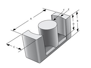
Available in various sizes, Magnetics powder core shapes compare favorably with gapped ferrites, powdered iron and silicon steel cores. In addition, for very large core requirements, these large shapes can be configured and bonded into a number of custom designs. Shapes include E core, U core, EQ core, EER core, LP core, Cylinder, Block, and Round Block.
Kool Mμ Shapes
Ideal for high current inductors, Kool Mμ geometries offer all the advantages of Kool Mμ material: low core loss, excellent performance over temperature, near zero magnetostriction and soft saturation.
Available in: Block, Cylinder, E, EER, EQ, LP, Round Block, U
Kool Mμ MAX Shapes
Kool Mμ MAX provides 50% better DC bias than standard Kool Mμ and is suitable for high efficiency, high power inductors.
Available in: Block, Cylinder, E, EER, EQ, LP, Round Block, U
Kool Mμ Hƒ Shapes
Kool Mμ Hƒ exhibits 35% lower losses compared to Kool Mμ and is a cost-effective solution for minimizing power losses in high frequency power supplies.
Available in: Block, Cylinder, E, Round Block, U
XFlux Shapes
XFlux is ideal for low and medium frequency inductors and chokes. XFlux is characterized by its high saturation (1.6 Tesla), which is advantageous in applications where inductance under load is critical.
Available in: Block, Cylinder, E, EER, EQ, LP, Round Block, U
High DC Bias XFlux® Shapes Available in: Block, Cylinder, E, Round Block, U
High Flux Shapes
High Flux is characterized by its high saturation flux density (15,000 gauss) and relatively low losses. High Flux shapes may be used in applications involving high power, high DC bias, or high AC bias at high power frequencies.
Available in: Block, Cylinder, E, EER, EQ, LP, Round Block, U
Edge Shapes
Edge displays both excellent DC bias capability and low losses - approximately 30% improvement in DC bias and 40% lower losses compared to High Flux. Choose Edge for highest efficiency.
Available in: Block, Cylinder, E, EER, EQ, LP, Round Block
Click here to enter the Magnetics part number(s) and download individual datasheets.
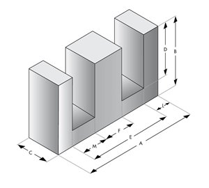
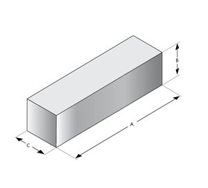
E cores Blocks
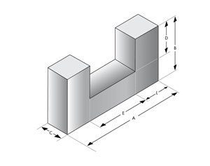
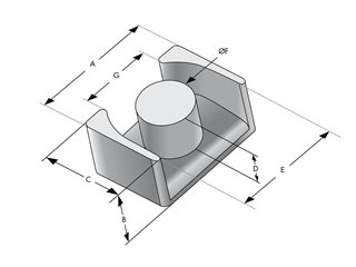
U Cores EQ Cores

Materials and DC Bias
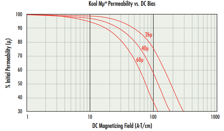
The most critical parameter of a switching regulator inductor material is its ability to provide inductance or maintain permeability under DC bias. The chart below (Figure 1) shows the reduction of permeability as a function of DC bias for Kool Mu material. The distributed air gap of powder cores results in a more gradual drop in inductance with increased DC bias. In most applications, this swinging inductance is desirable since it improves efficiency, decreases the volume needed and accommodates a wide operating range. With a fixed current requirement, the soft inductance versus DC bias curve provides added protection against overload conditions.
Leakage Flux
Leakage Flux occurs when some of the magnetic field is not contained within the core structure. All transformers and inductors have some amount of leakage flux. In an idealized core with no leakage flux, inductance is calculated using the following equation:

In low permeability material the effect of leakage flux is that measured inductance is higher than the inductance calculated using the equation shown above. The increase in measured inductance compared with calculated inductance, due to leakage, is strongly affected by the number of turns and the coil design and geometry. These effects can also extend to DC bias performance and core loss.
Effects on performance under DC bias can be seen inthe sample tests shown below. U-core inductors wound on only one leg show a marked decrease in performance compared to the same cores with windings distributed over 2-legs, which yields performance comparable to E-cores and toroids.

Click on image to view larger
Effects on core loss can also be seen in the sample tests shown below. U cores wound on only one leg have a noticeable decrease in core loss, followed by the same U cores wound on 2-legs, then E cores, then toroids.
Click on image to view larger
Core dimensions also affect leakage flux. In the case of an E core, a core with a longer winding length will have less leakage than a core with a shorter winding length, and a core with less winding build will have more leakage than a core with more winding build. Magnetics' Kool Mu E cores are tested for inductance factor (AL) with full 100- or 200-turn coils. U core inductance factors are listed for 1-leg windings.
External Leakage Field
The external leakage field must be considered when using E cores, U cores, or block assemblies as the core shape affects the leakage flux. Powder core shapes (E cores, U cores, and blocks), where most of the core surrounds the winding, have a greater external leakage field than the toroidal shape, where the winding surrounds the core.
E cores, U cores, and blocks should not be assembled with metallic brackets since the leakage flux may cause eddy current heating in the brackets. The leakage field must be considered when laying out the circuit board. Components susceptible to a stray magnetic field should be spaced away from the core. For more information on this subject, download the white paper “Leakage Flux Considerations on Kool Mµ E Cores.”
Core Selection
In core selection, the following procedure can be used to determine the core size and number of turns. Only two parameters of the design application must be known: inductance required with DC bias, and the DC current.
1. Compute the product of LI2, where: L = inductance required with DC bias (mH), I = DC current (amperes)
2. Locate the LI2 value in Magnetics 2024 Powder Core Catalog pgs. 29-42. Follow this coordinate to the intersection with the first core size that lies above the diagonal permeability line. This is the smallest core size that can be used.
3. Inductance and core size are now known. Calculate the number of turns by using the following procedure:
a) The nominal inductance (AL in nH/T2) for the core is obtained from Table 2 in the Powder Core Shapes bulletin. Determine the minimum nominal inductance by using the worst-case negative tolerance (-8%). With this information, calculate the number of turns needed to obtain the required inductance in mH by using: N= (L x 10-6 / AL)1/2.
b) Calculate the bias in A•T/cm from: H = NI/le (with le in cm)
c) From the Permeability vs. DC bias curve (Figure 1), determine the roll-off in per unit of initial permeability for the calculated bias level.
d) Increase the number of turns by dividing the initial number of turns (from step 3a) by the per unit value of initial permeability. This will yield an inductance close to the required value. A final iteration of turns may be necessary.
4. Choose a wire or foil size and verify that the window fill that results is manufacturable. Duty cycles below 100% allow smaller wire sizes and lower winding factors, but do not allow smaller core sizes.
The LI2 values in the Magnetics 2024 Powder Core Catalog are based on a winding factor of 60% (40% for toroids) and an AC current which is small relative to the DC current. LI2 values are based on the nominal inductance of the chosen core size and a permeability of 26. The current carrying capacity of the wire is 600 A/cm2. If a core is chosen for use with a large AC current relative to any DC current, such as a flyback inductor, a slightly larger size may be necessary. This will assist in reducing the operating flux density of the AC current that generates core losses. LI2 values only apply to blocks when assembled into a structure.
Special Designs
Many applications require a custom assembly or even a custom core. The material properties of powder cores and the flexibility of these geometries make the core ideal for custom assemblies.
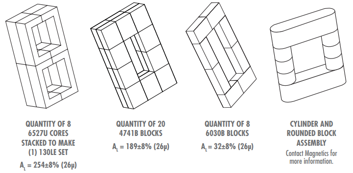
Download Block AL Calculator
Assembly Considerations
Discrete air gaps between powder core blocks are not generally needed because the air gap is inherent in the material. At the same time, extremely smooth mating surfaces (such as are employed with ferrites) are not required because the small incidental gap between blocks does not add appreciable extra gap and does not reduce inductance significantly.
The adhesives used for assembling blocks generally need to be thicker than those commonly used for ferrite assemblies, since powder core surfaces are rougher and more porous. Cores may require a double application of adhesive to ensure a strong bond.
Download "powder core shapes" bulletin