Learn More About Common Mode Filter Design
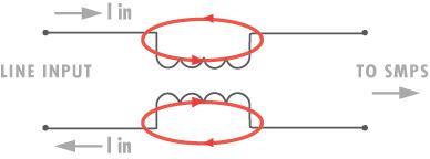
In a common mode (CMN) filter each winding of the inductor is connected in series with one of the input power lines. The connections and phasing of the inductor windings are such that the flux created by each winding appears to cancel (actually sums to zero within the core material) the flux generated by its opposing winding. The insertion impedance of the inductor to the input power line is therefore negligible.
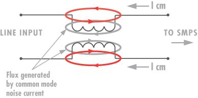
The two figures below illustrate both the flux generated by the power lines and that induced by any common mode noise present on the lines. While ‘power line’ flux sums to zero (often thought of as ‘canceling’) because of its opposing nature, the common mode flux is left unopposed and therefore encounters the high reactive impedance of the core material. This high impedance offers filtering action against the common mode noise.

Figure 1: Filter Reaction to Line Current

Figure 2: Filter Reaction to Common Mode Noise Current
Toroidal cores are most popular for CMN filters as they are inexpensive and have very low leakage flux. Toroids are typically wound by hand (or individually on winding machines), and so can have higher manufacturing costs than bobbin wound shapes such as EE and pot cores. However, the higher inductance allowed by having no inherent air gap at a mating surface can add as much as 30% more impedance at lower frequencies. Normally a non-metallic divider is placed between the two windings, and the wound unit is epoxied to a printed circuit header for attaching to a PC board.
View Software Features and Download Common Mode Filter Design