Powder Core Calculations
Winding Factor
Winding factor, also called fill factor, is the ratio of total conductor cross section (usually copper cross section) to the area of the core window. In other words, in a toroid, winding factor is given by:

Toroid Core Winding factors can vary from 20-60%, a typical value in many applications being 35-40%. In practice, several approaches to toroid winding are used:
- Single layer: The number of turns is limited by the inside circumference of the core divided by the wire diameter. Advantages are lower winding capacitance, more repeatable parasitics, good cooling, and low cost. Disadvantages are reduced power handling and higher flux leakage.
- Low fill: For manufacturing ease and reduced capacitance, winding factor between single layer and 30% may be used.
- Full winding: factors between 30% and 45% are normally a reasonable trade off between fully utilizing the space available for a given core size, while avoiding excessive manufacturing cost.
- High fill: Winding factors up to about 65% are achievable, but generally only with special expensive measures, such as completing each coil by hand after the residual hole becomes too small to fit the winding shuttle.
Mean Length of Turn
Winding turn lengths have been computed for each core size, using empirical relationships, for ten winding factors. This permits an estimate of actual length/turn for any winding factor.
MLT (Mean Length Turn) DCR Calculation
Calculating nominal DC Resistance for a single layer winding is straightforward. The mean length of turn (MLT) is simply the length of any turn along the surface of the core. MLT data can be found on each core data page. Then,

Even easier, Magnetics has calculated the single layer DCR for a range of wire gauges for each core size. See 2024 Powder Cores Catalog pgs 148-190.
Calculation Method
Calculate the winding factor for the core, wire gauge, and number of turns selected. On the wire table look up resistance per unit of length for the gauge selected.
On the data page for the core selected, consult the Winding Turn Length chart. Unless the winding factor is exactly one of the values listed, interpolate to find the MLT.
Wound Coil Dimensions
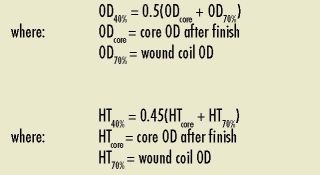
Wound coil dimensions are listed for 70% winding factor, as these are the largest dimensions necessary for packaging the wound coil. These dimensions are attainable. As a 70% winding factor (no residual hole) yields the same overall coil dimensions as a 100% (unity) winding factor (no interstices). Coil dimensions for coils wound to 40% winding factor can be estimated as follows.

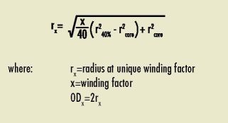
For other winding factors, OD dimension can be approximated by:

Temperature Rise Calculation
Heat to be dissipated in a magnetic component arises from energy losses due to DC resistance in the coil (I2R); AC copper losses, if high frequency AC current is present; and AC core losses, if AC current is present. (DC current does not result in any core losses, regardless of the magnitude.) Heat dissipation and temperature rise (ΔT) depend on many factors, so there is no simple way to predict ΔT precisely. But the following formula is useful for approximating ΔT for a component in still air.

Surface Area is that of the wound component. In this catalog, surface area is presented in two ways:
1. Unwound, coated core
2. Wound core, assuming 40% winding factor
Need more assistance?