Designing with Magnetic Cores at High Temperatures
All cores are not the same! Designers must know the differences in order to make the best choices.
Thermal considerations are a basic part of power electronics design. Components can be heated by external sources, and they can be heated by their own energy losses. Inductors and transformers are often designed for significant temperature rise in order to optimize cost, size, and performance therefore it is important for the Magnetics designer to understand the behavior of magnetic cores at elevated temperatures. Having this understanding is vital for selecting the best type of material for each application, and for ensuring that the magnetic device will function safely at its maximum operating temperature.
Powder Cores
Powder Cores made by Magnetics® are MPP (Molypermalloy), XFlux®, XFlux® Ultra, Kool Mµ®, Kool Mµ® MAX, Kool Mµ® Hƒ, Kool Mµ® Ultra, High Flux, 75-Series and Edge®. All materials exhibit excellent stability and reliability at high temperatures. Because of the distributed air gap in a powder core, the inductance shift with temperature change is relatively small. Due to the high Curie temperatures of powder core alloys, changes in saturation characteristics are minor over normal operating temperature ranges. Also, powder cores are resistant to thermal shock. All materials are rated for continuous operation up to 200°C.
No Thermal Aging
Magnetics powder cores have an advantage over iron powder cores – no thermal aging. The parts are pressed with a non-organic insulating material and no binder is used; therefore, there are no aging effects even when the cores are operated continuously at high temperatures.
For additional information on the effects of temperature on core loss of alloy powder cores, view our whitepaper.
Ferrite Cores
Magnetics Ferrite Cores are manufactured in seven standard materials. Each material has been engineered to satisfy particular application needs. (1) The five power materials (L, R, P, F and T) exhibit low core losses, and core loss minimums at favorable temperatures and frequencies. (2) The three high permeability ferrite materials (J, W, and M) show increasing permeability with increasing temperature. (3) The three filter materials (C, E and V) are designed for predictable or minimal inductance shift over a range of temperature.
Designers must be aware of ferrite magnetic property changes with temperature and that all ferrites are susceptible to thermal shock.
Tape Wound Cores
Magnetics manufactures Tape Wound Cores in a wide variety of materials and sizes. Tape cores can be placed in aluminum or nylon cases for very rugged environments and 200°C operation.
Tape core alloys generally have high Curie temperatures along with small, predictable shifts in magnetic properties across typical temperature ranges. They are often the best choice for very high temperature environments.
Choices, Choices
There are many considerations to be made when selecting the best core and material for a given application. Thermal performance is one of the most critical aspects of magnetic design. The designer needs to have a good understanding of the temperature advantages – and the disadvantages – of each material, all of which will be discussed in the following pages.
Powder Core Temperature Properties
Magnetics produces six types of powder cores. All have excellent high temperature performance.
MPP (molypermalloy powder) cores are made from an alloy of 80% nickel, 20% iron. The metal is ground into fine particles which are then coated with a non-organic, non-magnetic insulating material. The resulting powder is annealed at temperatures above 500°C, and finally pressed into toroids of a variety of sizes. The toroids are annealed above 500°C to relieve stresses. Finished toroids are coated with a gray epoxy paint to provide dielectric protection and extra physical mechanical strength.
Kool Mµ® cores are made from an alloy of iron, silicon and aluminum. Kool Mµ processing is similar to that of MPP cores, including powder annealing and core annealing above 500°C. Kool Mµ toroids are also coated with epoxy paint, except in black color. Kool Mµ is also available in E-cores, U-cores, LP cores, EQ cores, EER cores, and blocks with the similar temperature characteristics and performance. Shapes have slightly different DC Bias characteristics due to the differing geometry.
Kool Mµ® MAX powder cores, made of an alloy of iron, silicon, and aluminum, are an excellent choice for low core loss designs while still maintaining excellent DC bias performance. Priced between Kool Mµ and High Flux, Kool Mµ MAX cores prove to be cost efficient for a variety of applications. Toroids are coated in black epoxy.
Kool Mµ® Hƒ powder cores are the best option for achieving superior efficiency in medium and high current power inductors. With low losses in the target range of 200-500 kHz, Kool Mµ Hƒ was developed to serve the needs of SiC and GaN switching power supplies. Kool Mµ Hƒ can be used from 20 kHz up to several MHz while maintaining the same saturation and temperature performance benefits of Kool Mµ and Kool Mµ MAX. Toroids are coated in black epoxy.
Kool Mµ® Ultra's ultra low losses approach that of ferrite cores while maintaining powder core advantages of soft saturation, stable high temperature performance, and no gap fringing losses. With DC Bias also superior to standard Kool Mµ and comparable to Kool Mµ Hf, Kool Mµ Ultra is a great choice for datacom and telecom applications.
High Flux cores are made from an alloy of 50% nickel, 50% iron. Its manufacture is similar to that of MPP, including the 500°C anneals of powder and toroids. High Flux toroids are coated with the same epoxy paint in khaki color and additional shapes include EQ, LP, and EER cores.
XFlux® distributed air gap cores are made from 6.5% silicon iron powder and are available in a variety of permeabilities and shapes. A true high temperature material, with no thermal aging, XFlux offers lower losses than powder iron cores and superior DC Bias performance. These cores are available in toroids, E cores, U cores, EER cores, EQ cores, LP cores, and blocks. Toroids are epoxy coated and brown in color.
XFlux® Ultra cores offer the same high saturation found in standard silicon-iron XFlux while providing a 20% improvement in core loss. Applications include high efficiency uninterruptible power supplies (UPS), high power SMPS, and power factor correction (PFC) for on-board chargers (OBC).
Edge® cores are the best option for achieving smallest package size in high frequency, current-limited power inductors. When compared with High Flux, Edge achieves drastically improved DC bias performance and cuts AC core losses in half. Edge retains all the same advantages of soft saturation, high temperature performance, and minimal shift in properties with temperature. Toroids are epoxy coated and green in color.
75-Series cores are made from an alloy of iron, silicon, and aluminum like Kool Mµ but possess low core losses similar to XFlux. The relatively high saturation flux density of 75-Series cores makes them a low-cost solution in applications where stable inductance under load is necessary, such as inverters for renewable energy sources and Uninterruptible Power Supplies (UPS). Toroids are epoxy coated and black in color.
The maximum temperature rating for all Magnetics powder core materials is 200°C. The constraint is the epoxy coating, which is rated to 155°C or 200°C. In most circuits, there are many other components that would fail at lower temperatures, so the core is rarely the limiting factor. Inductors wound on Magnetics powder cores can withstand soldering operations that exceed the maximum rated temperature if care is taken in the design of the process to reasonably protect the core. Some applications even use potted inductors in excess of the rated maximum temperature, because the magnetic material itself is not damaged or aged, even at temperatures that are too high for the coating.
There is no aging effect when Magnetics powder cores are operated at elevated temperatures. This is often an advantage when compared with iron powders. Magnetics powder core materials do not contain an organic binder, and therefore are not subject to the thermal aging phenomenon seen in iron powder materials. In general, the main advantage of Magnetics powder cores is that core losses are much lower than with iron powder. They are also more stable with changes in temperature, frequency and drive level.
The magnetic properties of powder cores shift only slightly at high temperatures. The small changes in permeability, DC bias response, and core loss are reversible. When the materials are returned to room temperature, the magnetic properties return to their initial values, no matter how many times the cycle is repeated. For additional information on the effects of temperature specific to core loss, view our whitepaper.
Permeability vs. Temperature
The inductance shift with changing temperature in the powder cores is relatively small. This is largely due to the distributed gap, as well as to the stability of the alloys used. The following graphs show the typical change in inductance over temperature for Kool Mµ and MPP. The shifts are predictable and repeatable.
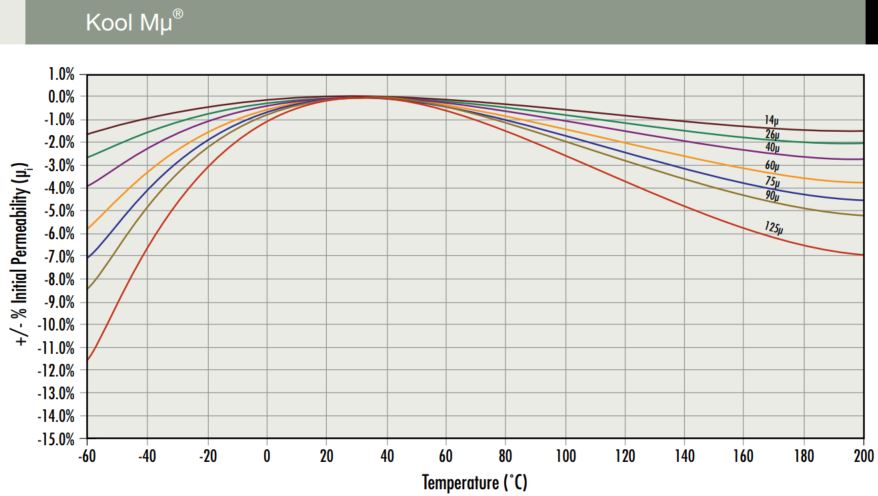
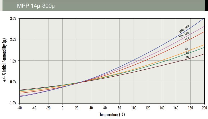
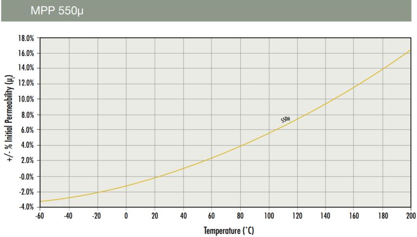
Figure 1. Permeability (hence inductance) changes no more than several percent, even at temperatures up to 200°C.
Even though the magnetic alloys used in the powder cores show greater changes in permeability with
temperature, the effective permeability of the material is dramatically stabilized by the presence of the distributed gap. The permeability in the gap, of course, is unity, no matter what the temperature is. Consequently, the lowest permeability cores, having the largest effective gaps, exhibit the most temperature stability. This effect is demonstrated in Figure 2 for six permeabilities of Kool Mμ.
Kool Mµ Permeability versus Temperature Curves
Figure 2. The lower the effective permeability of a gapped core, the less the permeability changes with temperature.
Permeability vs. DC Bias
Powder cores exhibit soft saturation. Due to the gap distributed microscopically through the material, powder cores do not reach saturation flux density (Bsat) all at once. Permeability rolls off, gradually and predictably losing its value at higher and higher magnetizing levels.
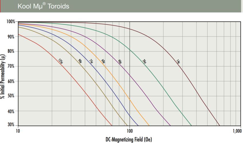

Figure 3. Permeability vs. DC Bias graphs for powder core materials.
| Material |
Alloy Composition |
Saturation Flux Density (Tesla) |
Curie Temp. |
Operating Temp. Range |
60µ, µ flat to... |
| Kool Mµ |
Fe Si Al |
1.0 T |
500°C |
-55 to 200°C |
5 MHz |
| Kool Mµ MAX |
Fe Si Al |
1.0 T |
500°C |
-55 to 200°C |
13 MHz |
| Kool Mµ Hf |
Fe Si Al |
1.0 T |
500°C |
-55 to 200°C |
16 MHz |
| Kool Mµ Ultra |
Fe Si Al |
1.0 T |
500°C |
-55 to 200°C |
3 MHz |
| MPP |
Fe Ni Mo |
0.75 T |
460°C |
-55 to 200°C |
2 MHz |
| Edge |
Fe Ni |
1.5 T |
500°C |
-55 to 200°C |
15 MHz |
| High Flux |
Fe Ni |
1.5 T |
500°C |
-55 to 200°C |
1 MHz |
| XFlux |
Fe Si |
1.6 T |
700°C |
-55 to 200°C |
4 MHz |
| XFlux Ultra |
Fe Si |
1.6 T |
700°C |
-55 to 200°C |
2.5 MHz |
| 75 Series |
Fe Si Al |
1.5 T |
700°C |
-55 to 200°C |
500 kHz |
Table 1. Powder Core Materials Comparison
The saturation characteristic shown by powder cores varies by only a couple of percent, even across quite wide temperature ranges. Figure 3 plots permeability vs. DC bias for all Powder Core materials. The reduction in saturation flux density with increasing temperature is not nearly as severe for the powder core alloys as for ferrites. The Curie temperatures are much higher, so typical electronics operating temperatures are well below the levels at which Bsat in the alloy begins to roll off significantly.
Thermal Shock
Unlike ferrites, powder cores are resistant to thermal shock. They routinely pass the most stringent military and aerospace thermal shock testing of electronic components. Although uncommon, one possible way in which a toroidal powder core may crack due to thermal effects is for the window to be wound so full of wire that the expansion of the copper with heat puts a greater tensile strain on the core than it can support. This is rare, partly because it is not natural for an economical winding process to result in such a full window.
Temperature Ratings
As noted above, all Magnetics powder core materials are normally rated for continuous operation up to 200°C which is quite adequate for nearly all power electronics applications. After pressing, the powder cores are given a stress-relief anneal for several hours at temperatures above 500°C. It is after this anneal that an epoxy paint to applied for dielectric protection and extra physical strength. So there is no doubt that 200°C has no damaging effects on the cores, even if applied continuously.
Inductors wound on powder cores can withstand soldering operations that exceed 200°C, if care is taken in the design of the process to reasonably protect the coating. Certain applications even use potted inductors with cores at temperatures greater than 200°C. This is possible because the magnetic material itself is not damaged or aged, even when operated at temperatures that are too high for the coating. The Curie temperature is 500°C for Kool Mµ, Kool Mµ MAX, Kool Mµ Hƒ, Kool Mµ Ultra, Edge, and High Flux, 460°C for MPP, and 700°C for XFlux, XFlux Ultra and 75-Series. Some small powder cores are coated with Parylene C, an organic conformal material. This is the “-AY” coating. The maximum rating for Parylene is typically 130°C. Again, if care is taken in setting up the process, inductors using the -AY coating may be exposed to soldering temperatures in excess of 130°C.
©Parylene C is a trademark of Union-Carbide Corp.
Core Loss and Temperature Rise
The more AC current or ripple current that an inductor sees, the more significant the core losses will be. DC current, of course, does not contribute to core loss, only copper loss. The loss curves for powder core materials are not significantly affected by the DC bias operating point, since the hysteresis loops are so dramatically flattened by the distributed gap.
Naturally, losses are seen as heat, which results in temperature rise. The designer’s task is to pick the optimum powder core material for his or her application, including consideration of the core losses. All other things being equal, at typical power frequencies, Kool Mµ Hƒ shows the best losses, followed by Edge, MPP, Kool Mµ MAX, Kool Mµ, High Flux, 75-Series, XFlux, and iron powder.
The powder core catalog contains graphs of core losses, as well as equations for those curves. The losses are given as a function of frequency and flux density for the various permeabilities of each material. Losses do not vary significantly with temperature (which is not the case for ferrites). Calculating temperature rise is discussed in the section on ferrites below.
Since iron powder is lossier than the other materials, an inductor will tend to run hotter with an iron powder core than with a similar sized, similar permeability powder core. The iron powder manufacturers provide curves and design notes that help the designer to set operating conditions that allow for thermal aging effects. Again, none of Magnetics powder cores contain an organic binder, and they are not susceptible to aging effects.
Shapes
Because of the high compaction forces needed to press the alloys without a binder, Magnetics powder cores traditionally were manufactured only in toroids. Magnetics now offers E, U, EQ, LP, EER, Block, Round Block, Segment, and Cylinder geometries in multiple materials.
The high temperature properties of Kool Mµ, High Flux, and XFlux are the same whether in toroid or other shapes. This includes a slight decrease in inductance at higher temperatures; no aging effect at elevated operating temperatures; and only a small shift in the permeability vs. DC bias characteristic with temperature. And since there is no coating, E-Cores could be qualified for use at much higher temperatures.
Ferrite Core Temperature Properties
Magnetics produces a complete line of Manganese-Zinc (Mn-Zn) ferrites. There is a broad selection of both materials and shapes. Toroids are available with several coating options, and shapes are available in a wide range of gap configurations.
Mn-Zn ferrites are dense, homogeneous ceramic structures made by mixing iron oxide (Fe2O3) with oxides or carbonates of one or more metals such as manganese, zinc, nickel, or magnesium. The oxides are precisely blended with a binder into powder. The powder is pressed into a variety of shapes, and the resulting parts are sintered in kilns at around 1000°C. Firing drives off the binder, and the result is a magnetic, ceramic material that is useful in a variety of applications. The fired parts are then machined or coated as needed.
Two distinctions should be made:
- Ferrites are ceramics, not metal alloys. Powder cores and tape wound cores are examples of alloys.
- Nickel-Zinc ferrites often used in EMI suppression are different from the Mn-Zn ferrites made by Magnetics and described here. (Mn-Zn ferrite also has many EMI suppression applications.) Magnetics ferrite materials mainly fall into one of three families:
Power Materials (L, R, P, F and T) are engineered for low core losses, allowing designers to minimize size and temperature rise, and to maximize efficiency. These materials are typically used in transformers and power inductors from 20kHz to 3Mhz. Core losses are minimized at different temperatures. L material exhibits the lowest losses at frequencies over 500 kHz.
High Permeability Materials (J, W, and M) are engineered for: (1) high permeability and impedance over frequency and (2) low loss factor. The initial permeabilities are 5000 (J), 10,000 (W), and 15,000 (M). These materials are typically used in broadband transformers and common mode inductors, and they exhibit little or no reduction in permeability as the temperature increases from 25°C.
Low Level Materials (C, E and V) are engineered for low loss factors and for characteristic temperature factors for use at low drive levels, such as in filter inductors. (Temperature factor is a function of the shift in permeability with temperature.) In addition to filters, they are used in many specialty applications.
Ferrites do not have a practical maximum rating for temperature, but the designer needs to be aware of their characteristics.Technically, the absolute maximum temperature rating of a ferrite is its sintering temperature, the point at which the ceramic material becomes reactive with oxygen. This is generally in the vicinity of 700°C to 900°C.
Ferrites can be the best choice for high temperature applications, but it is necessary to take into account several factors: Curie point; thermal shock; limitations of coatings and bobbins; and the shift (over temperature) of losses, permeability and saturation.
Curie Temperature
Each ferrite material has a characteristic Curie temperature. The permeability is at its maximum just below this point. Above Curie temperature, the core permeability sharply disappears, and the material is no longer magnetic while it is above TC.

Figure 4. R material Curie temperature is 210°C
The Curie temperature is predictable for each material, and every core will be close to the published value.
| Material |
TC |
Material |
TC |
|
R
|
210°C |
C
|
200°C |
| P |
210°C |
E |
160°C |
| F |
210°C |
V |
170°C |
| T |
220°C |
J |
145°C |
| L |
300°C |
W |
135°C |
Table 2. Ferrite Core Curie Temperatures
Ferrites are not damaged by exceeding the Curie point, even if done repeatedly or for extended periods. The magnetic properties return, unchanged, when the core cools down.
Similarly, ferrites show no aging effects or material degradation due to prolonged high temperature operation. The ceramic material is thermally stable. The change at the Curie point is in magnetic properties, not physical structure.
Thermal Shock
Because they are ceramic, ferrites can easily crack if exposed to rapid changes in temperature (thermal shock.) The material becomes vulnerable when it is changed by 4°C to 8°C or more per minute. An increase or decrease of 2°C or 3°C per minute is generally safe.
Ferrites are poor thermal conductors, which is a benefit in relation to thermal shock. A short exposure to high temperature (such as a soldering operation) is often too brief to cause core heating or cracking. Likewise, after cores have been assembled into wound units, and possibly taped, varnished, potted and attached to other components, the thermal shock seen by the core can be quite different from the nominal changes in temperature due to manufacturing, testing or operation. Testing of prototypes is essential whenever there is a possibility of thermal shock to the core.
Three common ways that thermal shock can crack ferrites are:
- (1) Sudden quenching to room temperature after a baking or curing operation.
- (2) Grinding the cores without adequate lubrication. (Grinding makes a lot of heat, all applied at a single point. Generous amounts of water should be used.)
- (3) Thermal shock testing of a bare wound core.
Coatings
Ferrite toroids are available in two standard coatings: Z and Y. Both present a smooth winding surface. Z and Y provide dielectric isolation and a second layer of insulation after the magnet wire varnish.
Z coating (Epoxy) is rated at 200°C. Very large and very small cores are coated with an epoxy finish.
The voltage breakdown guarantee of epoxy coating is 1000 volts wire to wire.
Y coating (Parylene C®) is a vacuum deposited coating providing good resistance to moisture and organic solvents. Electrical characteristics are superior to other coatings. It is offered on small toroids and rated to 130°C for continuous operation. Parylene can be exposed for brief periods to soldering temperatures up to 200°C.
Bobbins and Headers
Various plastics are used in the ferrite hardware. The Magnetics ferrite catalog lists the materials used in bobbin and toroid mounts. Temperature and flammability data is also included.
Loss vs. Temperature
Power materials are engineered to have characteristic core loss curves over temperature. When the loss minimum is at an elevated temperature, designers can make transformers and inductors that are smaller and more efficient, stabilizing at lower temperatures.
Core Loss vs. Temperature
L Material

R Material

P Material

F Material

T Material

Figure 5. P material has its lowest losses at 90°C to 110°C. R material, at 80°C to 100°C. F and T materials have their lowest losses at 60°C -80 °C and 60°C -100°C respectively.
Transformers or inductors that are designed to operate beyond the material’s core loss minimum are vulnerable to thermal runaway. As the core heats, it becomes less efficient, resulting in even more heating. Only when the device is so hot that the emitted energy catches up with the escalating loss energy, does it stabilize.
The observed temperature rise depends heavily on environmental factors such as ambient temperature, airflow, geometry, and the thermal conductivity of all the materials involved. A useful first cut equation relates the surface area of the magnetic with the total losses to yield an approximate temperature rise (from room temperature, in still air):
Rise (°C) = [Total Loss (mW) / Surf. Area (cm2)]0.833
For example, assume a transformer with copper and core adding up to about 0.6 W, and having a surface area (top, sides and bottom of the wound device) around 15 cm2. Then the approximate ΔT is [600/15].833 = 22°C.
Other factors that should not be overlooked are skin and proximity effects in the copper conductors, and fringing effects. The fringing problem occurs with gapped cores, where flux at the gap can intersect with copper near the gap and generate eddy currents. It is possible for the losses due to those eddy currents to exceed the total core losses in the inductor.
Ferrite material selection is also frequency-dependent. For example, R, P, and F materials are useful across a wide range of frequencies, even into the MHz, while L material has superior losses at high frequencies (500 kHz to 3 MHz.)
Permeability vs. Temperature
In all ferrites, permeability is sensitive to temperature. The temperature-dependency of permeability is predictable for each material, and it can be used to the designer’s advantage. (Of course, permeability is sensitive to other factors as well, especially flux density. Consult the ferrite catalog for data on the shift in permeability with flux density.)
As already noted, there is a primary peak in permeability that occurs just below the Curie temperature. There is typically a secondary peak that is seen at a lower temperature, characteristic for each material, and with greater or lesser amplitude.
In typical power materials, the permeability is not a critical factor. Inductance relates to exciting current, and so long as a reasonable primary inductance is achieved, changes in inductance with temperature or drive are much less significant than changes in loss characteristics. There is a loose correlation between the shape of the permeability vs. temperature curve and the permeability vs. core loss curve.
Permeability vs. Temperature
L Material

R Material

P Material

F Material

T Material

Figure 6: Power materials are typically used at flux levels and temperatures that increase the permeability. These curves are taken at 1000 Gauss (0.1 T) drive.
For high permeability ferrites, the permeability change with temperature is much more significant. The natural tendency for high permeability materials is to exhibit a saddle shape, or a minimum value, typically between room temperature and 75°C or 100°C. This is undesirable, since a designer does not wish to see, for example, decreased impedance if his or her common mode choke heats up. Magnetics cores are engineered to eliminate the saddle shape, so that the permeability is nearly flat or increasing with increasing temperature. (Figure 7.)
J Material

W Material

M Material
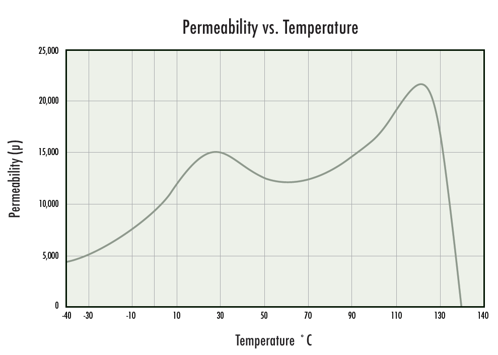
Figure 7. Magnetics high permeability materials exhibit nearly flat or positive shift in permeability with temperature.
In gapped cores, the measured µe vs. temperature curve is greatly flattened. The air gap results in an effective permeability (µe) for the core that is much lower than the bulk material permeability. (The same effect is seen in distributed gap powder cores.) The gap permeability is constant over temperature (unity), and therefore the combined effective permeability is much closer to a constant value. The deeper the gap, the more the gap dominates, and the flatter the µe vs. temperature curve will be. (Figure 8.)

Figure 8. The deeper the gap, the more the µe vs. temp. curve is flattened. Even an ungapped core set has enough air at the mating surface to flatten the curve significantly.
Some applications, such as filter inductors, require very flat or linear inductance over temperature. Often powder cores are the best solution, but ferrites are also used. Linear ferrites are produced with tightly controlled permeability vs. temperature characteristics. These are then made into cores, typically pot cores, and a gap is selected for the core. The gap value is chosen to balance the requirement for a certain minimum inductance against the need to sufficiently flatten the effective permeability curve.
Linear ferrite designs are controlled by specifying the temperature factor (TF) or the effective temperature coefficient (TCe). TF is a measure of the ppm shift in material permeability per degree C. TCe is the product of the TF and the µe of the gapped core, yielding a measure of the shift in the gapped core. The deeper the gap, the lower the µe, and therefore the lower or flatter the TCe.
C Material

E Material

V Material

Figure 9. The low level materials are engineered for filter applications. V is quite flat in the 20°C to 80°C range. C is fairly flat in a wider temperature range. E is linear, with a temperature factor (TF) to match that of some capacitors. See the ferrite catalog) for TF data and design notes.
Saturation vs. Temperature
In all ferrites, saturation flux density (Bsat) declines as the temperature goes up. In many applications, to keep the losses low, cores are not operated near saturation. But the designer needs to verify that the reduction in Bsat at elevated temperature will not interfere with the operation of the device.
Figure 10 below shows the flux density characteristic of a high temperature power material. In practice it would be unusual for a transformer to approach the saturation values shown, especially at frequencies above 30 or 40 KHz. At typical switching frequencies, transformers are designed for flux densities that result in maximum desired core loss. The designer sets the flux density (B) low enough for tolerable losses, but high enough to use a suitably small core. If a good power ferrite is used, the resulting B level is well below saturation, even at very high temperatures. Good power ferrites exhibit high Curie temperatures and high Bsat at temperature, in addition to their low losses and their elevated minimum loss temperatures.

Figure 10. Bsat vs. temperature for a power ferrite (R) and a high permeability ferrite (J).
Ferrite cores are used in inductors by employing a discrete gap, created by grinding down on the center leg or by separating the core halves with spacers. The gapped core will store a certain amount of energy, depending on the depth of the gap, the size of the core, and the material saturation. Figure 11 illustrates the saturation effect in inductors. Magnetics’ µe vs. H curve is used to verify that an inductor will not saturate at maximum current.

Figure 11. Maximum DC Bias for gapped ferrite cores.
Due to the discrete gap in a ferrite inductor, saturation with bias must be considered differently than with a powder core. The powder core distributed gap results in soft saturation, which means predictable, steady roll-off. In contrast, ferrite saturation is sharp, and the designer must take care to stay below the saturation point, hence the “Maximum DC Bias” parameter given inFigure 11.
For an inductor that will operate at elevated temperature, the maximum bias level is derated by the same percentage that the Bsat for the material decreases for that temperature. For example, comparing Figure 10 with Figure 11, it can be seen that R material shifts 22% from 25°C to 100°C. The saturation decreases by 22%, and therefore the maximum H level is derated by the same amount.
Tape Wound Core Temperature Properties
One of the primary advantages of toroidal tape wound cores is that they can operate in extreme environments, including extreme temperatures. Tape wound cores are often found in applications where ruggedness and small size are at a premium: aerospace, military, harsh industrial processes, and petroleum drilling.
In most cases, the tape core maximum continuous operating temperature is limited by the case or coating. Cores are placed in cases in order to protect the strain-sensitive magnetic material from physical stresses. Also, coatings and cases serve to prevent windings from being damaged by the sharp corners on bare cores. Temperature ratings by material and case are summarized in Table 3 below. See the Magnetics’ Strip Wound Cores catalog for additional information.
Tape core alloys are not damaged or aged by high temperatures. Typical temperature ratings for cases, coatings, wire and other components are far below alloy temperature limitations.
Magnetic properties of tape core alloys are less sensitive to temperature than those of ferrites. The percentage shift in saturation and core loss is relatively small. For example, Bsat of permalloy is typically reduced 8% - 9% at 125°C compared with 25°C. Bsat for Orthonol® typically shifts 9% to 11% in the same interval.
Nevertheless, some tape core applications rely on precise, repeatable B-H loop response, and temperature compensation in the circuit may be necessary. Consult the Magnetics application note Fundamentals of Tape Wound Core Design for more information.

N.A.-Not Available N.R.-Not Recommended
Table 3. Tape core temperature ratings.
Table 5. Powder core Curie temperature ratings.